Thank you for purchasing the Switch-Pros PowerTray and Dual MRBF accessory Bundle. Please follow the provided instructions to ensure that your PowerTray is installed correctly and the whole system is wired up correctly.
This install was done on a 2020 Toyota Tacoma TRD Off Road with automatic transmission. However steps should be almost identical for the 4th and 5th gen 4Runner's, FJ Cruiser's and GX460/470's.
Before you start check to make sure you have everything:
PowerTray Components:
- Switch-Pros PowerTray
- Support Leg
- Installation Hardware:
- (2) M8 JIS Flange Bolt
- (1) M6 JIS Flange Bolt
- (1) M6 JIS Flange Nut
- Accessory Hardware:
- (10) #8 x 9/16” Length Phillips machine screws
- (2) #8 x 3/8” Length Phillips machine screws
- (1) Rubber grommet
Accessory Bundle Components:
- Blue Sea 6 circuit fuse block
- Blue Sea 8 circuit terminal block
- Blue Sea 10 screw busbar
- Dual MRBF fuse holder
- 125A Marine Rated Battery Fuse
- 100A Marine Rated Battery Fuse
- 26" Length 4GA Power Cable
- 24" Length 4GA Power Cable
- 3’’ Length 4GA Ground Cable
- 16" Length 4GA Ground Cable
- Perma-Seal Heat shrink ring terminals
- Optional - Low-profile mini add-a-fuse's
Not included by PowerTrays:
PREP WORK: THINGS TO DO BEFORE THE INSTALL IN YOUR TOYOTA
1) Begin by prewiring the Switch-Pros output leads to the Positive Terminal Block.
- Mount the Switch-Pro and Blue Sea components to the PowerTray using the provided Accessory Hardware.
- The Busbar secures with the shorter 3/8" length machine screws; Everything else uses the longer 9/16" length machine screws)

- Route the Switch-Pros wires down under the unit and up though the space in the PowerTray.
- Temporarily hold the wires in place by removing the Terminal Block’s screws and reinserting them with the wire under the screw head.

- Once all 12 wires are routed and secured under the screw heads, adjust them for aesthetic uniformed length. Begin cutting them one by one using the edge of the Positive Terminal Block as a guide. This will ensure they are all uniform in length. (If your wire cutters are too bulky to get in there, use a pen or marker to mark a cutline on the wires so they can be removed and cut)

- Once all the wires are cut, flip the PowerTray over and begin stripping the ends in order to crimp on the heat shrink ring terminals. Lastly apply heat to the terminals to fully seal.


-
Note: Remove the Switch-Pros base module from the tray before attaching the wires to the terminal block. This will give the ring terminals more room while screwing them to the Terminal Block. Once the ring terminals are secured to the terminal block, move the SP's base back into location while using the back of the SP to uniformly push all the ring terminals down. Then finish screwing the SP's base into the vertical mounting tabs.


-
Pro Tip: The insulation will be pressing against the back of the base module. So slightly wedge your finger between the the two to help add some distance between them so they don't rub.

- Lastly, attach the Negative Stubby Cable taking special care to its orientation as the cable is made with reversed lugs to account for the height differences between the fuse block and busbar.


2) Run the SP harness though the firewall
Unfortunately I don't have any pics of this process at the moment. But one strategy that we use, is to poke a zip tie though the main wiring harness boot on the drivers side firewall. Poke the zip tie through from inside the cab so the connector and be pulled back through. Then tape the connector to the zip tie in a way that creates a gradual slope; so the connector doesn't get hung up on anything when pulling it back though into the cab. Electrical tap works best because it's stretchy and smooth. Also use some type of lube around the outside of the tape to help it squeeze though the factory wire harness boot on the firewall.
Tip: When taping the connector to the zip tie, start a little higher up on the zip tie and wrap towards the connector. This does two things; First it provides layers to act as the slope so the tape doesn't get hung up when going through the rubber boot; Secondly, starting up higher on the zip tie provides more surface area for the tape to adhere to.
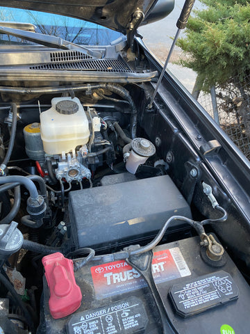
Installing The PowerTray
Check to make sure nothing is in the way. (This customer has a relay holder mounted right where the PowerTray mounts; This relay will no longer be needed as their light bar can now be wired directly to the Switch-Pros.)

Pro tip: Remove the factory fuse box cover so you have more room to get a hand under the PowerTray. You can also angle the PowerTray up and rotate it for better access on the first bolt.
Hold the PowerTray with your right hand and use your left hand to begin threading the M8 flange bolts into the factory threaded holes. Continue to hand tighten the first bolt until snug. For the second bolt, slide the PowerTray back (towards the cab) and the factory threaded hole will be right below the front edge of the PowerTray. Again, install the bolt until snug. We'll come back to finish tightening these after the PowerTray is positioned exactly where we want it.


Attach the support leg to the inside lip on the PowerTray with the included M6 hardware. Tighten until snug.

The bottom of the support leg attaches to a factory bolt that holds a bracket for the front differential breather lines (Two black tubes with silver caps). First remove the bolt, then add the support leg and reinstall the bolt until snug. It should be assembled in the following order: Bolt > Support Leg > Bracket > Fender.


Final Step: All the hardware should now be snugly installed. First slide the tray forward/backwards until its spaced evenly between the factory fuse box and master cylinder. Then use a small 1/4" drive ratchet with a 12mm socket to finish tightening the two M8 flange bolts on the fender side.
Its a little tight under the PowerTray, so just take your time on this step. If your big beef-cake arms just cant get this step done then some folks have found it easier to use a combination of extensions/swivel sockets in order to bring the ratchets handle out past the edge of the PowerTray.

Make sure the support leg is straight up and down and not angled. Then use a 10MM ratchet or wrench to finish tightening the connection at the top of the support leg. Note: The serrations on the M6 flange nut will bite into the aluminum support leg when you tighten the bolt. Simply hold the nut firmly in your fingers while you tighten the bolt and let science do the rest.
The lower support leg is the last connection we need to address. before tightening make sure the PowerTray is level. Pro tip: reinstall the factory fuse box cover for a level reference. The surface of the fuse box cover should run parallel to the surface of the PowerTray.

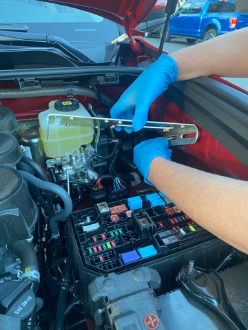
Wiring Switch-Pros Ignition and light sense wires: (Photo Dump)
The Switch-Pros has three voltage sensing wires used to control some of the features showcased by the unit. The light blue wire is the ignition sense wire and it is required in order to turn on and begin programing the Switch-Pros. The other taps are optional and used as a light sense (White wire used to dim the switch panel when you turn your lights on at night) and a trigger tap (Pink wire, this will be unique to each build, some have used this to tap into their reverse lights to simultaneously tigger aftermarket backup lights).
Step 1 - The following steps are optional. Group the 3 wires together and wrap approximately 18 inches of Techflex (supplied by Switch-Pros) and seal both ends with heatshrink.


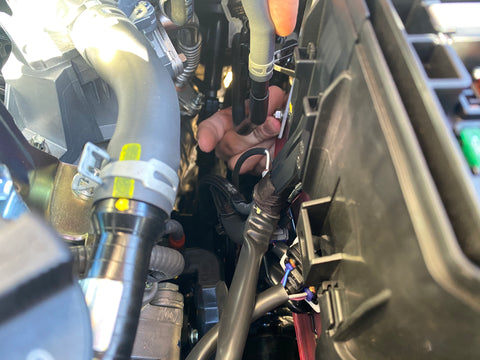
Step 2 - Bring the wires up into the factory fuse box by following the factory wires.
These pictures show how to use a zip-tie to aid in bringing the wires up into the factory fuse box.


Note: I then added another piece of tape wrapped in the opposite direction. This is so the tape doesn't get hung up when pulling the bundle up through. Also use some lubricant to help it slide though.


Step 3 - Use your Low-Profile add-a-circuit fuse taps to make the final connections.
Note: Factory fuse box layouts may vary depending on your specific year/options. These connections were made on a 2018 Tacoma TRD Off Road. (Fuse tap closest to the engine was the ignition sense and the tap closest to the fender was used as the light sense)


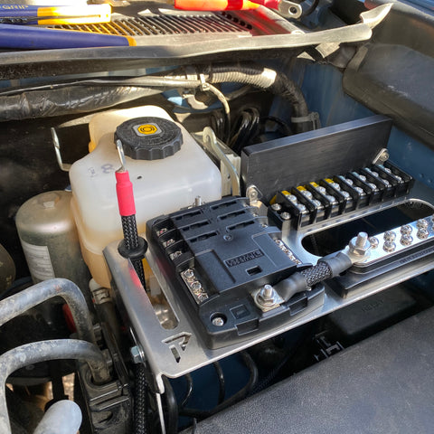
Cable Routing for Dual MRBF install:
Pretty self-explanatory from the pictures but the Dual MRBF mounts directly to the batteries positive post and provides the circuit protection for both the Blue Sea 5025 fuse block (100A) and Switch-Pros 9100 (125A).
Install the rubber grommet first; Then push the 24" fuse block cable through from underneath. We make the fuse block cable with a smaller 6 gauge battery lug to better fit through the rubber grommet. Note: If the grommet wants to pop out when pushing the cable through, use some lubricant on the lug/heat shrink area and wiggle the cable in a circle motion to slowly get through the rubber grommet.